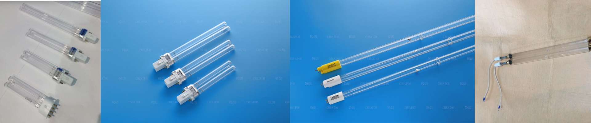
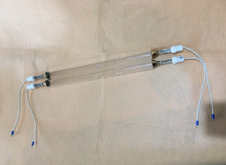
Getting Your PCB Lines Sharp with GaI Lamps
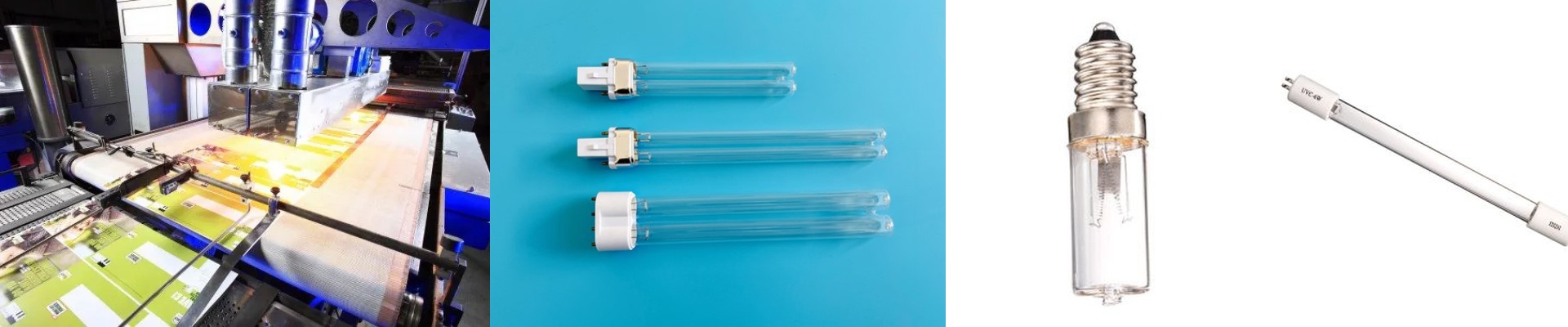
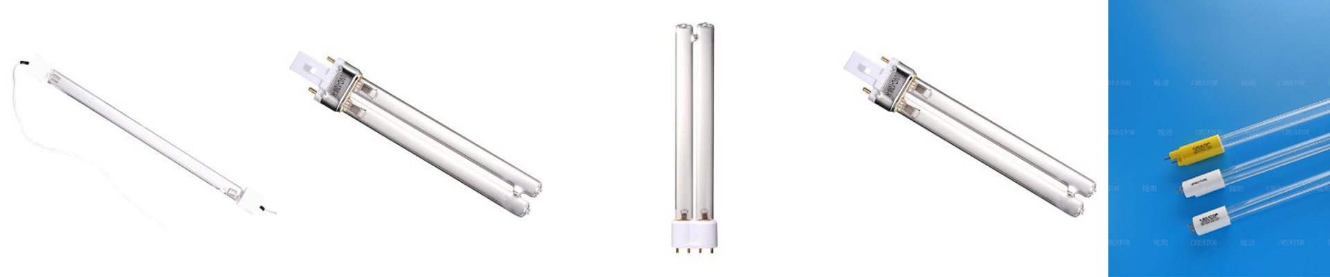
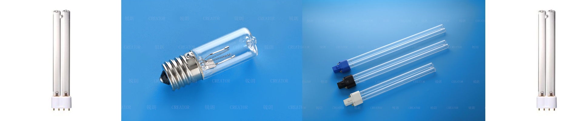
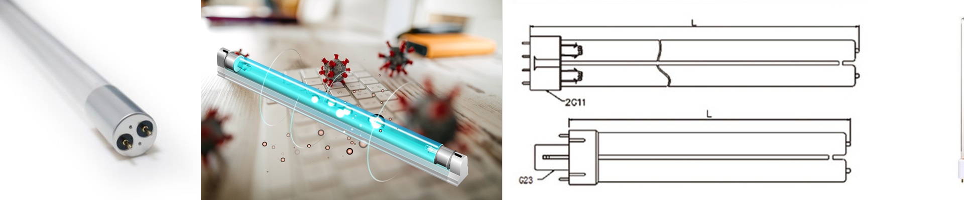
If you’re running a PCB shop, you know the drill. You need those ultraviolet wavelengths to hit just right to get the photoresist to react. Most people talk about “brightness,” but honestly? That’s not what actually matters here. What really counts is where that energy is sitting. We’re talking about narrowing that peak down to a 0.5% tolerance. It’s all about hitting that exact nanometer range so your circuit patterns stay crisp. The problem with “bleed” Here’s the thing: most UV lamps are messy. They leak energy all over the spectrum. For an engineer, that “bleed” is a nightmare because it causes light to scatter. You end up with blurry etched lines instead of sharp edges. We fix this by being obsessive about the gallium iodide fill and the pressure inside the quartz envelope. When we tighten those variables, the lamp stops guessing and starts emitting a concentrated spike of energy. No more blur. Just clean lines. The catch (and how to handle it) Now, there is a trade-off. When you push spectral density this high, heat becomes your biggest enemy. The lamp has to stay at a very specific temperature to keep the output stable. If your cooling system drifts by even a few degrees, the spectral peak shifts. Suddenly, your exposure times are off. If your conveyor speed or air pressure isn’t locked in, you’re just throwing boards in the trash. Putting it into your line The good news is that these are drop-in replacements. You can slide them right into your current UV arrays and use your existing power supplies. Just do yourself a favor and double-check that your ballast can handle the impedance of the GaI fill. And here is a nice little bonus: because the energy is so concentrated, you can usually shave time off your exposure. That means less heat hitting the machine and way less chance of your PCB substrate warping while it cures. It just makes the whole process feel smoother.